


Stimmen - 3, Durchschnittliche Bewertung: 3
(

 )
)
|
Fotos und technische Daten Indesit PI 640 A (WH)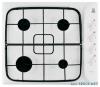 |


Anleitung Zusammenfassung
Cleaning the applianc. Gas tap maintenanc. PI 64. PI 640 . Troubleshooting, 2. PI 640 A. PI 640 AS. PI 640 A . GB Installatio. ! Before operating your new appliance please rea. this instruction booklet carefully. It contains importan. information for safe use, installation and care of th. appliance. ! Please keep these operating instructions for futur. reference. Pass them on to possible new owners o. the appliance. Positionin. ! Keep packaging material out of the reach o. children. It can become a choking or suffocatio. hazard (see Precautions and tips). ! The appliance must be installed by a qualifie. professional according to the instructions provided. Incorrect installation may cause harm to people an. animals or may damage property. ! This unit may be installed and used only i. permanently ventilated rooms in accordance wit. British Standard Codes Of Practice: B.S. 6172 / B.S. 5440, Par. 2 and B.S. 6891 Current Editions. Th. following requirements must be observed. . The room must be equipped with an air extractio. system that expels any combustion fumes. Thi. may consist of a hood or an electric fan tha. automatically starts each time the appliance i. switched on. In a chimney stack or branched flue. (exclusively for cooking appliances) Directly to the Outside . The room must also allow proper air circulation, a. air is needed for combustion to occur normally. Th. flow of air must not be less than 2 m3/h per kW o. installed power. AExamples of ventilation holes for comburant air. The air circulation system ma. take air directly from th. outside by means of a pip. with an inner cross section o. at least 100 cm2; the openin. must not be vulnerable to an. type of blockages. Enlarging the ventilation slot between window and floor. Adjacent Room to be RoomVented The system can also provid. the air needed for combustio. indirectly, i.e. from adjacen. rooms fitted with air circulatio. tubes as described above. However, these rooms must no. be communal rooms. bedrooms or rooms that ma. present a fire hazard. . Liquid petroleum gas sinks to the floor as it i. heavier than air. Therefore, rooms containing LP. cylinders must also be equipped with vents to allo. gas to escape in the event of a leak. As a resul. LPG cylinders, whether partially or completely full. must not be installed or stored in rooms or storag. areas that are below ground level (cellars, etc.). It i. advisable to keep only the cylinder being used i. the room, positioned so that it is not subject to hea. produced by external sources (ovens, fireplaces. stoves, etc. ) which could raise the temperature o. the cylinder above 50°C. Fitting the applianc. Gas and mixed hobs are manufactured with type . degree protection against overheating. The followin. precautions must be taken when installing the hob. . Kitchen cabinets adjacent to the appliance an. taller than the top of the hob must be at least 60. mm from the edge of the hob. . Hoods must be installed according to their relativ. installation instruction manuals and at a minimu. distance of 650 mm from the hob. . Place the wall cabinets adjacent to the hood at . minimum height of 420 mm from the hob (se. figure). 600mm min. 540mm min. 700mm min. If the hob is installed beneath . wall cabinet, the latter must b. situated at a minimum of 70. mm above the hob (see figure). . The installation cavity should have the dimension. indicated in the figure. GBIE 14 GB IE Fastening hooks are provided, allowing you to fasten the hob to tops that are between 20 and 40 mm thick. To ensure the hob is securely fastened to the top, we recommend you use all the hooks provided. 555 mm 55 mm 475 mm Hook fastening diagram 20 30 Hooking position Hooking position for top H=20 mm for top H=30 mm Front 40 Hooking position Back for top H=40 mm ! Use the hooks contained in the .accessory pack. . Where the hob is not installed over a built-in oven, a wooden panel must be installed as insulation. This must be placed at a minimum distance of 20 mm from the lower part of the hob. Ventilation To ensure adequate ventilation, the back panel of the cabinet must be removed. It is advisable to install the oven so that it rests on two strips of wood, or on a completely flat surface with an opening of at least 45 x 560 mm (see diagrams). Where a hob is installed above an oven without a forced ventilation cooling system, adequate ventilation must be provided inside the cabinet by means of air holes through which air can pass (see figure). ! The PI 640 AST hob can only be installed above built-in ovens with a cooling ventilation system. Electrical connection Hobs equipped with a three-pole power supply cable are designed to operate with alternating current at the voltage and frequency indicated on the data plate (this is located on the lower part of the appliance). The earth wire in the cable has a green and yellow cover. If the appliance is to be installed above a built-in electric oven, the electrical connection of the hob and the ove...