


Stimmen - 1, Durchschnittliche Bewertung: 4
(

 )
)
|
Fotos und technische Daten Husqvarna 235FR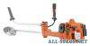 |


Anleitung Zusammenfassung
• Only use the recommended trimmer heads and trimmer cords.These have been tested by the manufacturer to suit a particular engine size.This is especially important when a fully automatic trimmer head is used. Only use the recommended cutting attachment. See the chapter on Technical data. • Smaller machines generally require small trimmer heads and vice versa. This is because when clearing using a cord the engine must throw out the cord radially from the trimmer head and overcome the resistance of the grass being cleared. • The length of the cord is also important. A longer cord requires greater engine power than a shorter cord of the same diameter. • Make sure that the cutter on the trimmer guard is intact. This is used to cut the cord to the correct length. • To increase the life of the cord it can be soaked in water for a couple of days.This will make the line tougher so that it lasts longer. English – 11 ASSEMBLY Fitting the handlebar (232R) • Remove the screw at the rear of the throttle handle. • Remove the screw at the rear of the throttle handle. • Slide the throttle handle onto the right side of the • Slide the throttle handle onto the right side of the handlebar, (see diagram). handlebar, (see diagram). • Align the screw hole in the throttle handle with the hole in the handlebar. • Refit the screw in the hole in the rear of the throttle handle. • Screw the screw through the handle and handlebar. Tighten it. • Unscrew the knob from the handlebar mounting. • Position the handlebar as shown. Fit the mounting components and tighten the knob lightly. • Put on the harness and hang the machine from the support hook. Now make a final adjustment so that the machine is in a comfortable working position when it hangs from the harness. Tighten the knob. Fitting the handlebar (235R, 235FR) • Align the screw hole in the throttle handle with the hole in the handlebar. • Refit the screw in the hole in the rear of the throttle handle. • Screw the screw through the handle and handlebar. Tighten it. • Remove the mounting components from the handlebar mounting. • Position the handlebar as shown. Fit the mounting components and tighten the knob lightly. • Fit the wiring as shown. • Put on the harness and hang the machine from the support hook. Now make a final adjustment so that the machine is in a comfortable working position when it hangs from the harness. Tighten the knob. 12 – English ASSEMBLY Transport position, handlebar • The handlebar can easily be turned to fit along the shaft for easier transportation and storage. • Loosen the knob.Turn the handlebar clockwise so that the throttle handle rests against the engine. • Now twist the handlebar around the shaft. Tighten the knob. • Fit the transport guard to the cutting attachment. Assembling the cutting equipment ! WARNING! When fitting the cutting attachment it is extremely important that the raised section on the drive disc/support flange engages correctly in the centre hole of the cutting attachment. If the cutting attachment is fitted incorrectly it can result in serious and/or fatal personal injury. ! WARNING! Never use a cutting attachment without an approved guard. See the chapter on Technical data. If an incorrect or faulty guard is fitted this can cause serious personal injury. IMPORTANT! If a saw blade or grass blade are to be used the machine must be equipped with the correct handlebar, blade guard and harness. Fitting a blade guard, grass blade and grass cutter (232R) G F E D B C A L M • The blade guard (A) is fitted using 4 screws (L) and the support plate (M) as shown. CAUTION! Always use the recommended guard for the cutting attachment you are using. See chapter on Technical data. • Fit the drive disc (B) on the output shaft. • Turn the blade shaft until one of the holes in the drive disc aligns with the corresponding hole in the gear housing. • Insert the locking pin (C) in the hole to lock the shaft. • Place the blade (D), support cup (E) and support flange (F) on the output shaft. • Fit the nut (G). The nut must be tightened to a torque of 35-50 Nm (3.5-5 kpm). Use the socket spanner in the tool kit. Hold the shaft of the spanner as close to the blade guard as possible. To tighten the nut, turn the spanner in the opposite direction to the direction of rotation (Caution! left-hand thread). English – 13 14 – English ASSEMBLY Fitting a blade guard, grass blade and grass cutter (235R, 235FR) • Hook the blade guard/combination guard (A) onto the fitting on the shaft and secure with the bolt. CAUTION! Ensure that the guard extension is removed. Use the recommended blade guard. See the Technical data section. • Fit the drive disc (B) on the output shaft. • Turn the blade shaft until one of the holes in the drive disc aligns with the corresponding hole in the gear housing. • Insert the locking pin (C) in the hole to lock the shaft. • Place the blade (D), support cup (E) and support flange (F) on the output shaft. • Fit the nut (G). The nut must be tighten...