


Stimmen - 2, Durchschnittliche Bewertung: 4.5
(

 )
)
|
Fotos und technische Daten Furuno CH-300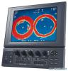 |


Anleitung Zusammenfassung
These units can be installed on a tabletop or flush mounted in a console or panel. 1.1.1 General mounting considerations • Keep the monitor unit out of direct sunlight. • Select a location where the unit(s) can easily be operated while observing the fishing ground or area surrounding the vessel. • For maintenance and checking purposes, leave sufficient space at the sides and rear of the unit and leave slack in cable. (Refer to the outline drawing at the back of this manual.) 1.1.2 Mounting Unibody type 1. Fasten the mounting base to the mounting location with four self-tapping screws (5X20). FRONT Mounting base 2. Fasten the bracket at the rear of monitor/control unit with four binding screws (M4x10). 1. MOUNTING 11 22 3 3 4 4 Bracket (rear view) Bracket, rear view 3. Coat threads of upset screws (M6x16, 2 pcs.) used to fasten bracket to mounting base. 4. Fasten the bracket to the mounting base with two upset screws. (Use the upper holes to tilt the monitor unit 20°; lower holes to tilt it 9°.) Upset Screw Bracket Mounting base For 9 tilt For 20 tilt Fastening bracket to mounting base 1. MOUNTING Flush mounting Flush mounting for unibody (Type: OP06-16, Code no.: 006-556-300) Name Type Code No. Qty Remarks Fixing metal 06-021-1311-2 100-279-612-10 1 Self-tapping screw 5x20 000-162-609-10 6 Hex. bolt M4x12 000-162-939-10 4 1. Cut out a hole (W287 x H297) in the mounting location. 2. Fasten monitor/control unit with the fixing metal (supplied) and four hex. bolts (M4x12, supplied). 3. Fasten the fixing metal assembled at step 2 to hole made at step 1 with six self-tapping screws (5x20, supplied). Hex. bolts Fixing metal 1.1.3 Mounting separated monitor unit 1. Fasten the mounting base to the mounting location with four self-tapping screws (5x20). FRONT Mounting base 2. Dismount the coupling plate to separate monitor unit from control unit. 3. Attach the bracket at rear of the monitor unit with four binding screws (M4x10). 1. MOUNTING 1 2 3 4 1 2 3 4 Bracket (rear view) Bracket, rear view 4. Coat threads of upset screws (M6x16, 2 pcs.) used to fasten bracket to mounting base. 5. Fasten the bracket to the mounting base with two upset screws. (Use the upper holes to tilt the monitor unit 20°; lower holes to tilt it 9°.) Flush mounting for monitor unit (Type: OP06-17, Code no. 006-556-310) Name Type Code No. Qty Remarks Fixing metal 06-021-1321-2 100-279-622-10 1 Self-tapping screw 5x20 000-162-609-10 4 Hex. bolt M4x12 000-162-939-10 4 1. Cut out a hole (W287 x H207) in the mounting location. 2. Fasten the fixing metal (supplied) to the monitor unit with four hex. bolts (M4x12, supplied). 3. Fasten the fixing metal assembled at step 2 to hole made at step 1 with four self-tapping screws (5x20, supplied). Hex. bolts Fixing metal 1. MOUNTING 1-5 1.1.4 Blackbox type The blackbox type requires a VGA monitor, connected via the interface unit IF-8000. Supply commercial monitor and interconnection cable (Max. length 15 m with Dsub-15P connectors of male, three rows of 15 pins). The monitor used should satisfy the specifications shown below. • VGA type • ANALOG RGB 0.7 Vpp, positive polarity • TTL level H, V, Negative polarity Note: The LCD monitor MU-151C does not require the interface unit IF-8000. For details, see the operator’s manual for MU-151C. 1.2 Control Unit For blackbox type, fix the control unit to the mounting plate (supplied as accessories). See the parts list of FP06-01120 and outline drawings at the back of this manual. 1. Fix the mounting plate to the place selected with two self-tapping screws (5X20, supplied). 2. Fix the bracket to the control unit with two hex. screws (M4X12, supplied). 3. Insert the screwdriver from the top of the mounting plate holes and then tighten two hex. screws (M4X12) loosely. 4. Attach the control unit to the mounting plate, and fasten two hex. screws tightly. 5. Attach two cosmetic caps to the holes at the top of the mounting plate. Cable entrance hole Mounting plate Cable Tapping screws (5X20) Fasten the screws to fix the bracket. Bracket Bracket Insert to the hex. screws tightened at step 3. Cable can be passed this direction. 6. Attach hard cover to protect the control unit. How to remove the hard cover Place your thumbs at the locations shown with circles in the illustration at right, and then lift the cover while pressing it with your thumbs. 1. MOUNTING To mount the control unit separate from the monitor unit, the optional control unit separate kit is required. Mount the control unit same as the above procedure. See the outline drawing at the back of this manual to mount. Type: OP06-15-1.5 NEW Code no.: 006-559-140: with 1.5 m cable Type: OP06-15-5 NEW Code no.: 006-559-150: with 5 m cable Name Type Code no. Qty Remarks Cable MJ-A10SPF0002-015 000-142-878 1 For 1.5 m cable MJ-A10SPF0002-050 000-131-411 For 5 m cable Bracket 06-021-2112 100-281-880-10 1 Mounting Plate 06-021-2111-1 100-279-741-10 1 Self-tapping Screw 5x20 000-162-608-10 2 Cosmetic Cap DP-687 000-165-997...
Dieses Handbuch ist für folgende Modelle:Boote Zubehör - CH300 (3.87 mb)