


Stimmen - 3, Durchschnittliche Bewertung: 4.3
(

 )
)
|
Fotos und technische Daten Antec Mini P180 White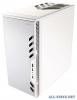 |


Dieses Gerät hat auch andere Anweisungen:
Netzteile - Mini P180 White (81.01 kb)
Netzteile - Mini P180 White (80.51 kb)
Anleitung Zusammenfassung
Mini P180 / Mini P180 White User’s Manual Manuel de l’utilisateur Anwenderhandbuch Manuale per l’operatore Manual del usuario ........... At Antec, we continually refine and improve our products to ensure the highest quality. As such your new case may differ slightly from the descriptions in this manual. This isn’t a problem; it’s simply an improvement. As of the date of publication, all features, descriptions, and illustrations in this manual are correct. Disclaimer This manual is intended only as a guide for Antec’s Computer Enclosures. For more comprehensive instructions on installing the motherboard and peripherals, please refer to the user’s manuals that come with those components. Mini P180 / Mini P180 White User’s Manual The Mini P180 is a small case that’s big on features. It is a professional case that is highly configurable. For that reason, this case comes without a power supply. Make sure you choose a power supply that conforms to the newest ATX standard and is compatible with your motherboard. Most ATX power supplies come with an on/off switch. Make sure you turn the switch to the ON (I) position before you boot up your computer for the first time. Normally, you won’t need to switch to the OFF (O) position, since the power supply includes a soft on/off feature. This lets you turn your computer on and off by using the soft switch on your computer case. If your computer crashes and you can’t shut it down using the soft switch, you can switch the main power to the OFF (O) position to clear the fault, then reboot. Setting Up 1. Place the case upright on a flat, stable surface with the rear of the case facing you. 2. Remove the thumbscrews from the right side panel. Grip the panel at the top and bottom and slide it towards you to open the case. 3. Remove the screws from the left side panel. Grip the panel at the top and bottom and slide it towards you to remove the left side panel. Note: Don’t use your fingernails to pry or lift the panels. Inside the case you should see two separate chambers — the upper chamber for motherboard, a 5.25” external drive and up to 5 hard drives; and the lower chamber for power supply and two bays for 5.25” external drives. The upper 5.25” bay will accommodate a CD or DVD drive up to 170mm in length. You will also find some wiring with marked connectors (USB, PWR etc.), drive rails for 5.25” drives, installed I/O panel, and a 5.25” to 3.5” drive bay adapter. Remove the middle hard disk cage to access the tool box which contains all the hardware screws, spare silicone grommets, and standoffs. Installing the power supply 1. With the case upright, install the power supply into the case. Note: You can mount the power supply either side up. If you have a power supply with a large fan, the fan should be on top once the unit is installed. 2. Between the two chambers a plastic structure lets you run cables between the upper and lower chambers. 1 Installing the Motherboard This manual does not cover CPU, RAM, or expansion card installation. Please consult your motherboard manual for specific mounting instructions and troubleshooting. 1. Lay the case down, with the open side facing up. The drive cages and power supply area should be visible. 2. Make sure you have the correct I/O panel for your motherboard. If the panel provided with the case isn’t suitable, please contact your motherboard manufacturer for the correct I/O panel. 3. Line up the motherboard with the standoff holes. Determine which holes line up and remember where they are. Not all motherboards will match with all of the provided screw holes, and this is not necessary for proper functionality. Some standoffs may be pre-installed for your convenience. 4. Remove your motherboard by lifting it up. 5. Install standoffs as needed and put the motherboard back in. 6. Screw in your motherboard to the standoffs with the provided Philips-head screws. Your motherboard is now installed. Cable Organizer Instead of running all the power cables into the upper chamber, they can be organized between the motherboard and right side panel. 1. Remove both side panels. 2. Choose the cables you would like to pass through the holes behind the motherboard tray and pull them out of the power supply chamber towards the right side of the case. 3. Route them up through the gap in the bar and use the cable ties to hold them in place. 4. Feed the cables back through the insertion point nearest the destination of the cable. Connect the cable and then pull the slack back to the right side of the case. 5. When finished, secure all cables with ties and put the right panel back in place. Connecting the Ports and LEDs 1. Connect the Reset switch (labeled RESET SW) to your motherboard at the RST connector. Polarity (positive and negative) does not matter for switches. 2. Power Switch (labeled POWER SW) connects to the PWR connector on the motherboard. 3. Power LED (labeled POWER LED) connects to the PWR header on the motherboard. For LEDs, colored wires ...
Dieses Handbuch ist für folgende Modelle:Computer-Zubehör - Mini P180 (78.77 kb)