


Stimmen - 4, Durchschnittliche Bewertung: 3.8
(

 )
)
|
Fotos und technische Daten Makita 6203DWAE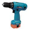 |


Anleitung Zusammenfassung
CAUTION: *The fast charger Model DC1410 is for charging Makita battery cartridge. Never use it for other purposes or for other manufacturer’s batteries. *When you charge a new battery cartridge or a battery cartridge which has not been used for a long period of time, it may not accept a full charge. This is a normal condition and does not indicate a problem. You can recharge the battery cartridge fully after discharging it completely and recharging a couple of times. *If you charge a battery cartridge from a just-operated tool or a battery cartridge which has been left in a location exposed to direct sunlight or heat for a long time, the charging light may flash in red color. If this occurs, wait for a while. Charging will begin after the battery cartridge cools. The battery cartridge will cool faster if you remove the battery cartridge from the fast charger. *If the charging light flashes alternately in green and red color a problem exists and charg- ing is not possible. The terminals on the charger or battery cartridge are clogged with dust or the battery cartridge is worn out or damaged. *If you wish to charge two battery cartridge, allow 15 mimutes between charging on the fast charger. ASSEMBLY Installing or removing driver bit or drill bit CAUTlON: Always be sure that the tool is switched off and the battery cartridge is removed before installing or removing the bit Hold the ring and turn the sleeve counter- clockwise to open the chuck jaws. Place the bit in the chuck as far as it will go. Hold the ring firmly and turn the sleeve clock- wise to tighten the chuck. Tighten To remove the bit, hold the ring and turn the sleeve counterclockwise. Slee:ve - Ring When not using the driver bit, keep it in the bit holders. Bits 45 mm (1-3/4") long can be kept there. Bit - I Bit holder 2 OPERATION Switch action CAUTION: Before inserting the battery cartridge into the tool, always check to see that the switch trigger actuates properly and returns to the "OFF" position when released To start the tool, simply pull the trigger. Tool speed is increased by increasing pres- sure on the trigger. Release the trigger to stop. 77- Switch trigger Reversing switch action CAUTIO N: *Always check the direction of rotation before operation *Use the reversing switch only after the tool comes to a complete stop. Changing the direction of rotation before the tool stops may damage the tool This tool has a reversing switch to change the direction of rotation. Depress the reversing switch lever from the A side for clockwise rotation or from the B side for counterclockwise rotation. When the switch lever is in the neutral position, the switch trigger cannot be pulled. Speed change To change the speed, first switch off the tool and then slide the speed change lever to the "11" side for high speed or "1" side for low speed. Be sure that the speed change lever is set to the correct position before operation. Use the right speed for your job. Reversing switch lever - Clockwise Counterclockwise 0Low speed a High speed Speed change lever CAUTION: *Always set the speed change lever fully to the correct position. If you operate the tool with the speed change lever positioned half-way between the "I" side and "11" side, the tool may be damaged. *Do not use the speed change lever while the tool is running. The tool may be damaged. Adjusting the fastening torque The fastening torque can be adjusted in 18 steps by turning the adjusting ring so that its graduations are aligned with the pointer on the tool body. The fastening torque is minimum when the number 1 is aligned with the pointer, and maximum when the 8 marking is aligned with the pointer. The clutch will slip at various torque levels when set at the number 1 to 5. The clutch is designed not to slip at the 8 marking. Before actual operation, drive a trial screw into your material or a piece of duplicate material to determine which torque level is required for a particular application. NOTE: *The adjusting ring does not lock when the pointer is positioned only half-way between the graduations. *Do not operate the tool with the adjusting ring set between the number 5 and the 8 marking. The tool may be damaged. Screwdriving operation Place the point of the driver bit in the screw head and apply pressure to the tool. Start the tool slowly and then increase the speed gradually. Release the trigger as soon as the clutch cuts in. NOTE: *Make sure that the driver bit is inserted straight in the screw head, or the screw and/or bit may be damaged. *When driving wood screws, predrill pilot Nominal diameter of Recommended size wood screw lmm) of pilot hole Imm) holes to make driving easier and to pre- vent splitting of the workpiece. See the 3 5 19/64") I 2 2 -2 5 13/32"-3/32") chart. 3.815/32") 1 2 5 -2.8 (3132'' -7/64',) *If the tool is operated continuously until the battery cartridge has discharged, allow the tool to rest for 15 minutes before proceeding with a fresh battery. Drilling operation Fir...