


Stimmen - 4, Durchschnittliche Bewertung: 4.3
(

 )
)
|
Fotos und technische Daten Pioneer DEH-2000MPB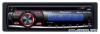 |


Dieses Gerät hat auch andere Anweisungen:
Car-Receiver - DEH-2000MPB (888.39 kb)
Car-Receiver - DEH-2000MPB (739.35 kb)
Anleitung Zusammenfassung
(При установке рамки ее сторона с канавкой должна быть внизу.) • Рамку легче снимать при снятой передней панели. 2 Выберите положения, при котором отверстия на кронштейне и боковых панелях устройства совпадают. 3 Закрутите по два винта с каждой стороны. Винт Монтажная рамка Приборная панель или консоль • Используйте винты либо с круглыми (5 мм х 8 мм), либо с плоскими головками (5 мм х 9 мм), в зависимости от формы отверстий под винты кронштейна. Н Закрепление передней панели Если Вы не собираетесь снимать переднюю панель, ее можно закрепить прилагаемым винтом. Винт в (Connections ) ( j 4 Note: Depending on the kind of vehicle, the function of 3* and 5* may be different. In this case, be sure to connect 2* to 5* and 4* to 3*. 1 This product P 2 Antenna jack / 3 Fuse (10 A) 6 Cap (1 *) Do not remove cap if this terminal is not in use. 7 Yellow (3*) Back-up (or accessory) 5 Connect leads of the same color to each other. _____/_______ Yellow (2*) Connect to the constant 12 V supply terminal. Red (5*) Accessory (or back-up) 10 Red (4*) Connect to terminal controlled by ignition switch (12 V DC). 11 Black (chassis ground) Connect to a clean, paint-free metal location. 12 ISO connector In some vehicles, the ISO connector may be divided into two. In this case, be sure to connect to both connectors. 13 Speaker leads White: Front left © White/black: Front left © Gray: Front right © Gray/black: Front right © Green: Rear left © Green/black: Rear left © Violet: Rear right © Violet/black: Rear right © En (Connections ) ( j 14 Wired remote input Hard-wired remote control adaptor can be connected (sold separately). 15 Yellow/black If you use an equipment with Mute function, wire this lead to the Audio Mute lead on that equipment. If not, keep the Audio Mute lead free of any connections. 16 Blue/white Connect to system control terminal of the power amp (max. 300 mA 12 V DC). /_ 17 Blue/white (7*) Connect to auto-antenna relay control terminal (max. 300 mA 12 V DC). ! Blue/white (6*) The pin position of the ISO connector will differ depends on the type of vehicle. Connect 6* and 7* when Pin 5 is an antenna control type. In another type of vehicle, never connect 6* and 7*. Fig. 1 Abb. 1 Afb. 1 Pmc. 1 En (Connections j ( j Important • When this unit is installed In a vehicle without ACC (accessory) position on the Ignition switch, red cable must be wired to the terminal that can detect the operation of the Ignition key. Otherwise, battery drain may result. ACC position No ACC position • Use of this unit In conditions other than the following could result In fire or malfunction. — Vehicles with a 12-volt battery and negative grounding. — Speakers with 50 W (output value) and 4 ohm to 8 ohm (impedance value). • To prevent a short-circuit, overheating or malfunction, be sure to follow the directions below. — Disconnect the negative terminal of the battery before Installation. — Secure the wiring with cable clamps or adhesive tape. To protect the wiring, wrap adhesive tape around them where they lie against metal parts. — Place all cables away from moving parts, such as gearshift and seat rails. — Place all cables away from hot places, such as near the heater outlet. — Do not pass the yellow cable through a hole Into the engine compartmen...
Dieses Handbuch ist für folgende Modelle:Car-Receiver - DEH-2000MP (735.38 kb)
Car-Receiver - DEH-2020MP (735.38 kb)